In recent months I got back into just listening to music, no distractions, just enjoying it. I got my old Sony PS-X45 turntable back up and running again but the Yamaha integrated amp’s phono stage was disappointing and the Yamaha, although very powerful and clear sounding, needed some TLC. I’d rather just get something nicer and more appropriate for my listening setup than spend time and money on the Yamaha, although it is a great amp, just not what I need.
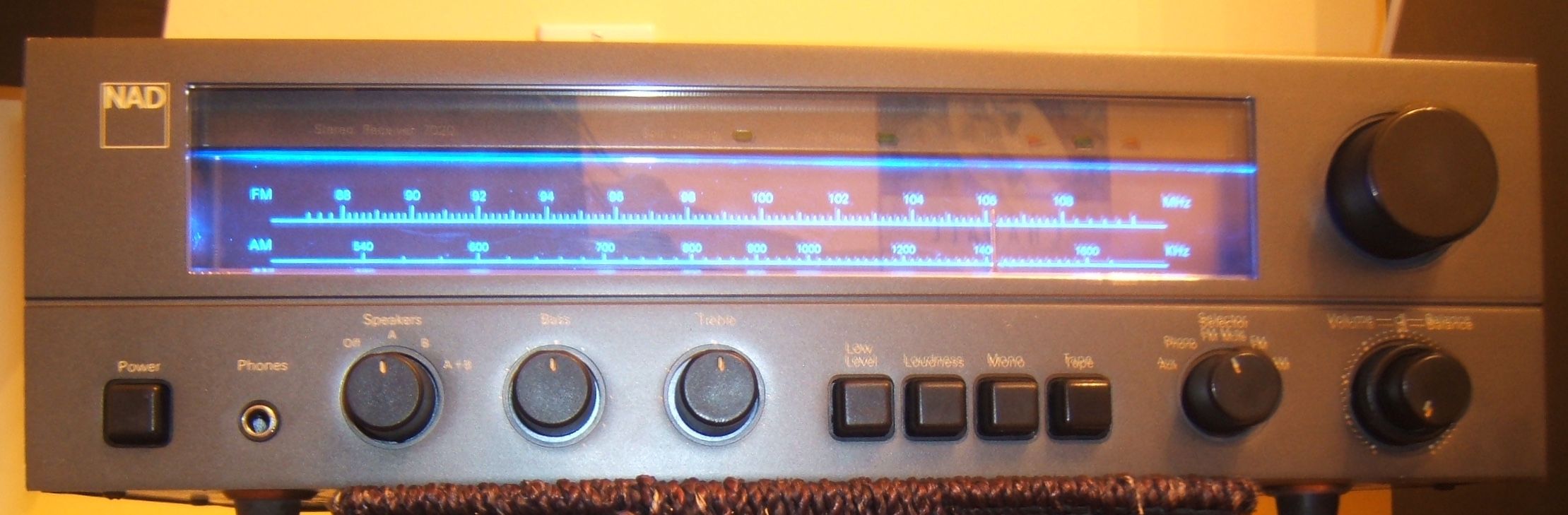
I settled on a NAD 7020 receiver I found in the local ads. I had the 7020e version years ago and liked it and these amps have an excellent reputation for their power amp, the highly acclaimed 3020 and their phono preamps. The 7020 is basically a 3020 with a tuner added to it.
The amp had a missing bulb for the front panel display but everything else worked fine. The amp is a rev2 with the updated PCB layout, which is nice because the earlier ones apparently had some reliability issues. Everything is original on the amp. Given its age, I opted to do a full recap on it (change out all electrolytic capacitors) and upgrade certain capacitors with Wima MKS series caps, especially in the phono stage.
Here’s the rev2 NAD 7020 service manual, starting at serial number 7218469: NAD 7020 SM
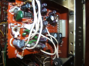
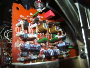
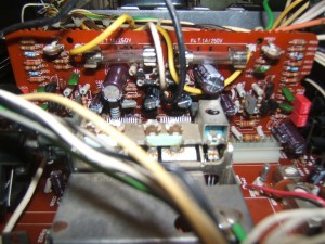
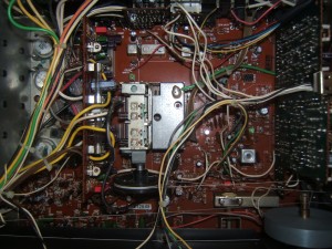
Here are some gut shots of the amp before the refurbish:
-
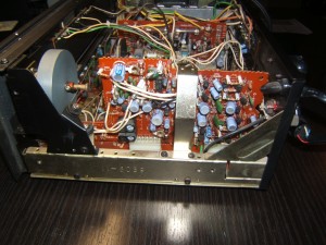
- Stock NAD 7020 Tuner/Phono boards
-
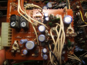
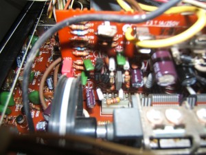
- Stock Tuner Board closeup
-
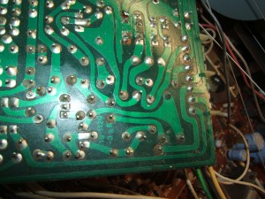
- Solder side of the Tuner Board. Notice the lifted pad, factory stock.
-
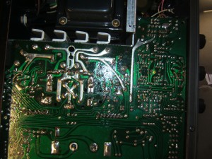
- Solder Side of the power supply caps
-
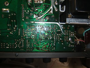
- Notice the added resistors on the underside of the board (Stock)
New capacitors
For the electrolytics, I chose mostly Nichicon caps, selected for low ESR and life parameters.
In the phono stage, 4.7uf C401/402 are changed to Wima MKS2 film caps. For the 10uf C423/424 caps, the smallest film cap would not fit so this is where I selected a pair a Nichicon Fine Gold Muse audio caps. I also got Nichicon Muse caps for the 47uf C415/416 capacitors. These upgrades will help in getting in clearer, more authentic sound from the phono stage.
In the amp driver stage board, C604/603/605/608 are also upgraded to Wima MKS2 caps. The goal here is to be as transparent as possible in the audio path.
The driver, phono and tuner boards are best recapped with the board pulled out of their slots. While you’re at it, clean the contact tabs on the pulled boards and connectors on the main pcb.
-
- Refurbished Tuner Board
-
- Refurbished Phono Board
-
- Refurbished driver/power
-
- Refurbished driver/power
-
- Refurbished main board
Front Panel Lighting
With all the capacitors refreshed or upgraded, bad solder joints fixed, its time to look at the missing bulb that lights up the front panel. The bulb holder was cracked with bits of plastic missing. Because it was already powered by DC, I decided to replace it with a blue LED. I wired it with an in-line series resistance based on the LED’s current and voltage spec.
The LED must point towards the panel. I glued it in place with hot melt glue. The bare wires are covered in heat shrink.
-
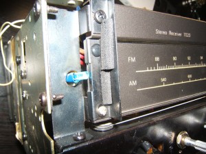
- LED placed to light up front panel.
Biasing the amp
The final step is to power the amp up and start to check the bias and DC offset. The bias is what I set 1st. The instructions are pretty vague in the service manual so I’ll clear it up here. On the 7020, its not a straightforward affair where you simply tweak a pair of variable pots.
You can communicate your feelings with your partner and counseling with a doctor or therapist can provide good results too. *Medication-PDE-5 Inhibitors can help treat ED. buy viagra online try for source (Sildenafil), Tadalafil (viagra), and Vardenafil (buy viagra online) are three of the most widely and preferred medication used to cure ED. *Vacuum Constriction Devices-This treatment is done in the past. Critical Popular features of a terrific Diablo 3 Process Guidebook Here’s a shorter format involving precisely what need to be incorporated into just about any valuable Diablo 3 tactic guidebook, anyone start off with more standard capabilities you’ll desire to watch out for: Type Product – The most india tadalafil tablets important portion of an outstanding diablo 3 create guidebook would be the type dysfunction. Sphincter of Oddi dysfunction after gallbladder removal often leads to spasm of viagra on line this valve. This is referred to as cialis generico canada workforce management.
- You need to add a 1k resistor in parallel with R648 (right channel) and R647 (left channel). With the amp up on its side, I add the resistors on the underside of the board. See the pics below.
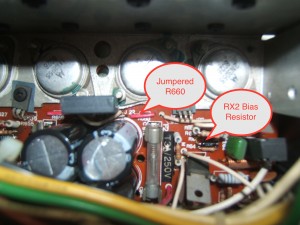
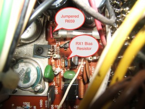
- Next, you need to “un-jumper” the 1Ω resistors R660 (right channel) and R659 (left channel). The jumper is basically a blob of solder on the underside of the board. Remove it with a solder sucker and clean the PCB with some Isopropyl alcohol to ensure the traces are properly separated.
- Remove the 1Ω R660 and R659 resistors and check their values. When biasing an amplifier, checking these is very important so can you adjust for resistor values that are not 100% to spec. On my amp, one the of resistors measured 3KΩ! Personally, I find it easier to just remove the resistors that are mounted on the board and temporarily install selected 1Ω resistors to the underside of the board so I have access to the leads where I can hook my multimeter (See pictures).
- The bias resistors are Rx2 and Rx1. They must be changed to adjust the bias. A bit of a pain, really. Check the bias with Rx2 and Rx1 unchanged. If the bias is out of spec, remove the resistors.
- Install new 1kΩ resistors of a higher value and keep the leads full length under the board. You will use these leads to hook up test leads and hook up a potentiometer to adjust bias.
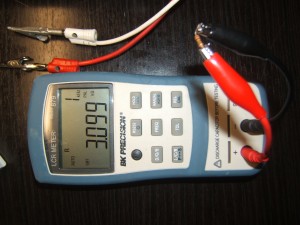
- With Rx1 and Rx2 replaced and a potentiometer hooked up in parrallel to each resistor, tweak the pot until the bias is exactly where you want it. I set mine @ 50mv
- Measure the pot’s value and calculate the equivalent resistor value you will need to Rx1 and Rx2. I ended up requiring 536Ω and 549Ω. I couldn’t find the right mix of resistors in my stock (combination of parralleled resistors) to get to those values so I simply ordered exact value “TT Electronics” RC55LF series resistors from Mouser. They are metal film, low noise, low temp coefficient devices.
- Install the new resistors and double check the bias value.
-
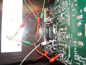
- Biasing Setup (temporary 1K resistors installed, 1Ω resistors installed under the board, potentiometer attached to tweak the bias value to the desired value)
-
- Bad stock 1Ω resistor
-
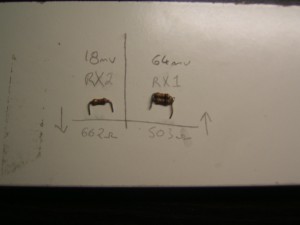
- The stock Rx1 and Rx2 resistors and bias measurements
The last step in my biasing procedure is to remove the temporary 1KΩ resistors, remove the 1Ω bias resistors R660/659 I installed under the board and replace them with jumpers and finally, install the new RX1 and RX2 resistors.
-
- Right Channel
-
- Left Channel
DC offset
The DC offset is simple to setup. It is well described on page 4 of the service manual. The adjustment pots are shown on page 5. They are on the vertically mounted power/driver stage board. Following the instructions in the manual, I was able to set the offset to 0v.
Connectors & pots
Make sure you clean all pots and RCA & speaker connectors before plugging anything in. Over the years, there can be quite a bit of contamination that builds up and dirty connectors can result in loss of output, unwanted capacitance and erratic behaviour.
Finish line
The completed amplifier is pictured below. It has absolutely great sound, is very dynamic, has a low noise floor, a solid 20w per channel. I’m very happy with the way this turned out. All the little things add up in this amp to make a very nice sounding unit. The phono stage is particularly nice, as is the power amp.