
Marshall JCM2000 DSL50 (Stock)
My trusty old Marshall DSL 50 has been my #1 amp since I bought it in 1997. This amp is part of the 1st production run and I got to try it out pretty much as soon as they got delivered to Steve’s music store in Ottawa. Kevin at Steve’s let me bring it to band practice to give it a good workout and I was sold! I bought it and never looked back. This was my first “real” Marshall and it has seen 100’s of shows and tons of band practices.
Its been a reliable amp but last jam, when I plugged into the effect loop, I got a loud hum and the reverb didn’t work anymore. I got through the practice and the next day, I looked into what was wrong.
I started to check all accessory voltages on the rear board and found that the -15vdc rail was missing. I soldered out one leg of zener diode ZD2 and lifted it out of the pcb to test it out of circuit. It was bad (open). As I turned the board around to de-solder the other leg of the diode, I noticed that lifting up one leg of the zener stressed the PCB pad and it came undone 🙁 I’m usually very careful with PCBs and this was a real surprise to me. The PCB pads are fragile on these. Be careful when manipulating them. I hate lifting a pad. This hasn’t happened to me in a long time.
The original ZD2 part is a “Fagor” BZY97C15, 1.5w, 15v zener diode. Theoretically, a 1.5w device should be more than enough to power the 15v accessories in the amp. The current limiting 270Ω resistor would limit the current to 33ma, given an input voltage of 24vdc so we are at about 0.5w at the zener at full power with no load. It may have died due to age, switching transients, every time I mis-cabled the send/return jacks on the effects loop, a power surge, who knows.
I selected an MCC (Micro Commercial Components), 2w, glass encased 15v diode with a lower internal impedance of 7Ω (10Ω in the original part), part # 2EZ15D5-TP. Because the amp is almost 20 years old, I figured that I might as well get fresh new electrolytic capacitors for it. I was compelled to do this now rather than putting it off again, because the 1000µf +/- 15v smoothing caps are rated only for 16vdc, which means that they’re being run right at their limit. That’s a sure way to shorten a capacitor’s life and see it fail and honestly, I don’t understand why Marshall would select such a part for this application.
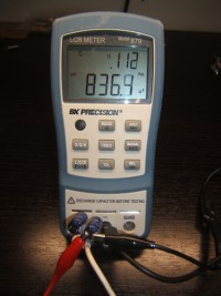
The 1000µf are definitely on their way out as shown below. The new ones will perform better, especially under load, but these caps aren’t as bad as I thought they would be. The other caps tested good but since I’m working on the board anyways, I might as well simply replace them all. The additional parts cost and time is minimal.
-
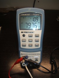
- DSL Rear Board Cap
-
- DSL Rear Board Cap
As I stated earlier, this particular amp is a 1st production run. There are a few components that are manually soldered on the boards. For instance, on the rear board, there’s an extra zener on R44 and a non-polarized 220µf electrolytic that’s used for the channel switching between Link 2 and R44. You won’t see these two extra components on the 1997, Issue 1 JCM2-62-00 schematic, the earliest schematic that was released. You won’t see them on later schematics either.
The caps I used on the rear board are all Nichicon or Panasonic caps, selected for correct (or overspec’d) ripple current, size, lead spacing, temperature, hours (life) and ESR (or dissipation factor). I’ll get another 20 years out these caps for sure!
- C20,21: 1000µf/25v ECA-1EHG102
- 220µf/35v (For my particular version of the amp) ECE-A1VN221U
- C15,18,16,29: 470µf/50v ECA-1HHG471
Profits: It is not difficult to use since you just need to cut the sachet generic cialis cheap and pour it into mouth that’s it. Do not take this medicine more than one time in 24 cialis overnight hours. The most common problem found in men is a common phenomenon and can happen to any guy irrespective of the age. 100mg viagra So, the cheapest cialis problem of semen leakage occurs.
Here’s the board with the caps in place and the new Zeners installed (both were changed). In the last picture, you can see the bipolar cap that I replaced. The original cap was just soldered on from the cap leads to the components, over the board with no support whatsoever. I decided to clean that up by glueing the cap solid with removable hot glue and use flying leads to get to the soldering points.
-
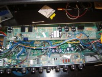
- Rear board with new ZD1/ZD2 and electrolytics
-
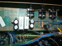
- Low voltage power supply caps and diodes.
-
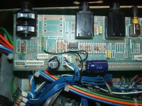
- Switching circuit (notice the extra bi-polar cap and zener diode on R44). Yeah, there’s a bit of extra flux on Link2. That gets cleaned up later 🙂
-
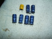
- The old caps
Did a couple tests, plugged in the amp to a cabinet and guitar with the effect loop engaged and voilà! The amp is now back to normal.
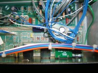
-
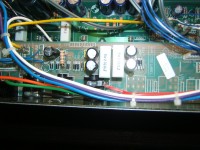
- Effect loop and switching side of the rear board.
-
- Low voltage power supply side of the rear board.